🧩 Zephyr SPI Notes for Nordic microcontrollers - Part 1

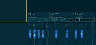 Image credit: [Me]
A hardware-first introduction to Zephyr SPI bring-up, focused on the definitions that must be correct before a device can respond.
At the electrical level, the SPI communication protocol looks straightforward: clock, data out, data in, and one chip-select per device.
In Zephyr RTOS, when an SPI device doesn’t respond, it’s tempting to blame the driver or the SPI API.
More often than not, especially on a custom board, SPI issues lie earlier: the wrong controller instance, an unassigned pin, a misplaced compatible string, an incorrect chip-select index, or a configuration detail that was assumed rather than verified.
In Zephyr, an SPI connection is described and enabled across several configuration mechanisms: devicetree defines the hardware and its boot-time configuration, pinctrl assigns peripheral signals to physical pins, and Kconfig enables the software support included in the firmware.
One of the most useful distinctions I have learned in Zephyr is that an SPI bus and the devices connected to it aren’t described in the same way.
The Nordic SPIM peripheral is the controller that represents the bus. Sensors, radios, converters, and other peripherals are child nodes on that bus. Their chip-selects, interrupts, pin assignments, and driver support are configured through related Zephyr definitions, but each belongs to a different node, parent-child relationship, or configuration label.
This is the first part of my Zephyr SPI learning notes. This post explores that separation through SPI configuration on the nRF52840, starting with devicetree, pinctrl, and prj.conf.
1. Mental model: bus and devices
In Zephyr devicetree, an SPI setup has two levels. The bus is the SPI controller node, and the devices connected to that bus are the SPI child nodes.
For instance, if an nRF52840 microcontroller is the SPI master, then other devices are SPI slaves connected to the same physical bus lines:
-> SCK
-> MOSI shared by all SPI devices
-> MISO shared by all SPI devices MISO
-> one separate chip-select per device
The important devicetree idea is:
&spi0 / &spi1 / &spi2 / &spi3
-> SPI controller / bus compatible = "nordic,nrf-spim"
-> belongs to the Nordic SPI controller

cs-gpios
-> belong to the bus, as an array

device1@0 / device2@1 / device3@2 / ...
-> SPI child devices, reg = <0>, <1>, <2>, ...
-> index into the cs-gpios array
So, reg doesn’t mean an SPI address. SPI doesn’t have I2C-style addresses. In this context, reg = <0> means: use entry 0 of the cs-gpios array.
RAK Wisblock example
&spi1 {
    compatible = "nordic,nrf-spi";
    status = "okay";
    cs-gpios = <&gpio1 10 GPIO_ACTIVE_LOW>;
    pinctrl-0 = <&spi1_default>;
    pinctrl-1 = <&spi1_sleep>;
    pinctrl-names = "default", "sleep";
    lora: lora@0 {
        compatible = "semtech,sx1262";
        reg = <0>;
        reset-gpios = <&gpio1 6 GPIO_ACTIVE_LOW>;
        busy-gpios = <&gpio1 14 GPIO_ACTIVE_HIGH>;
        tx-enable-gpios = <&gpio1 7 GPIO_ACTIVE_LOW>;
        rx-enable-gpios = <&gpio1 5 GPIO_ACTIVE_LOW>;
        dio1-gpios = <&gpio1 15 GPIO_ACTIVE_HIGH>;
        dio2-tx-enable;
        dio3-tcxo-voltage = <SX126X_DIO3_TCXO_3V3>;
        tcxo-power-startup-delay-ms = <5>;
        spi-max-frequency = <1000000>;
    };
};

&gpio0 {
    status = "okay";
};

&gpio1 {
    status = "okay";
};
Don’t put the Nordic SPI compatible in child nodes
Correct:
&spi3 {
    compatible = "nordic,nrf-spim";
    device3: optical-afe@2 {
        compatible = "vnd,spi-device";
        reg = <2>;
    };
};
Incorrect:
device3: optical-afe@2 {
    compatible = "nordic,nrf-spim";  // wrong
    reg = <2>;
};
nordic,nrf-spim describes the nRF52840 SPI master peripheral. It doesn’t describe the connected devices.
Generic child vs. real driver child
During early bring-up, it’s acceptable to use a generic SPI child:
compatible = "vnd,spi-device";
That means: “Zephyr, please describe this SPI connection, but my application code will manually send the SPI commands.”
Later, if you write a real Zephyr driver and binding for the device, the child may use a real compatible string:
compatible = "manufacturer,device";
At that point, the child is not only an SPI connection. It becomes a real Zephyr device instance backed by a driver.
Interrupt pins are separate from SPI
Some SPI devices also have interrupt pins. For example, many sensors may use an interrupt line to tell the MCU that data is ready.
That interrupt isn’t part of the SPI bus. It is a normal GPIO property of the child device:
device3: optical-afe@2 {
    compatible = "vnd,spi-device";
    reg = <2>;
    spi-max-frequency = <24000000>;
    int1-gpios = <&gpio0 8 GPIO_ACTIVE_HIGH>;
};
This only works cleanly when the binding used by that child node allows the interrupt property. For a generic bring-up node, keep only the properties accepted by the binding. For a proper custom driver, define the property in a custom binding such as manufacturer,device.yaml.
2. nordic,nrf-spim vs nordic,nrf-spi
On nRF52840 and newer microcontrollers, prefer:
compatible = "nordic,nrf-spim";
SPIM is the EasyDMA-capable SPI master peripheral. It is the typical choice for production SPI transfers.
Conceptually:
| Compatible | Meaning | Typical use |
|---|---|---|
nordic,nrf-spim | SPI master with EasyDMA | Preferred for nRF52840 SPI buses |
nordic,nrf-spi | Older/non-DMA SPI master style | Rarely preferred unless required by board/peripheral constraints |
SPIM is usually the right choice because:
- It supports EasyDMA transfers.
- It reduces CPU involvement during SPI transfers.
- It's the normal Nordic peripheral style used for higher-throughput SPI.
- It's better suited for repeated register transfers.
Important EasyDMA consequence
Because SPIM uses EasyDMA, SPI transfer buffers should live in RAM.
Good patterns:
uint8_t tx_buf[4] = { 0 };
uint8_t rx_buf[4] = { 0 };
static uint8_t tx_buf[16];
static uint8_t rx_buf[16];
Be careful with buffers that may be placed in flash/ROM, especially constant transmit buffers. If a low-level nrfx SPIM transfer receives a buffer address that is not accessible by EasyDMA, the transfer can fail.
For simple Zephyr application code, stack or static RAM buffers are usually the safest bring-up choice.
Instance choice matters for speed
On nRF52840, not every SPIM instance has the same capabilities.
A conservative rule for custom boards is:
For low-speed bring-up:
    almost any available SPIM instance can work.

For higher-speed SPI:
    prefer the high-speed-capable SPIM instance.
In practice, when using frequencies above 8 MHz, pay attention to the selected SPI instance. This is especially relevant if the devicetree uses something like:
&spi3 {
    compatible = "nordic,nrf-spim";
    status = "okay";
};
spi3 / SPIM3 is commonly the instance used when higher SPI speeds are needed on nRF52840.
However, don’t start bring-up at the maximum frequency. First probe the bus at a slow frequency, then increase speed only after identity reads and signal quality are stable.
3. Pinctrl pattern for nRF52840 SPI
In Zephyr, SPI pin assignment for Nordic nRF52 devices is usually done with pinctrl.
The SPI bus node references pinctrl states:
&spi3 {
    status = "okay";
    compatible = "nordic,nrf-spim";
    pinctrl-0 = <&spi3_default>;
    pinctrl-1 = <&spi3_sleep>;
    pinctrl-names = "default", "sleep";
    # cs-gpios and child devices here
};
The actual pin assignment is defined under &pinctrl:
A typical pinctrl definition looks like this:
&pinctrl {
    spi3_default: spi3_default {
        group1 {
            psels = <NRF_PSEL(SPIM_SCK, 0, 19)>,  # P0.19
                    <NRF_PSEL(SPIM_MOSI, 0, 21)>, # P0.21
                    <NRF_PSEL(SPIM_MISO, 0, 23)>; # P0.23
        };
    };
    spi3_sleep: spi3_sleep {
        group1 {
            psels = <NRF_PSEL(SPIM_SCK, 0, 19)>,
                    <NRF_PSEL(SPIM_MOSI, 0, 21)>,
                    <NRF_PSEL(SPIM_MISO, 0, 23)>;
                    low-power-enable;
        };
    };
};
Meaning of NRF_PSEL()
The Nordic pinctrl macro has this practical meaning:
NRF_PSEL(function, port, pin)
For example:
NRF_PSEL(SPIM_SCK, 0, 19)
means:
Route SPIM SCK to P0.19
And:
NRF_PSEL(SPIM_MOSI, 1, 10)
means:
Route SPIM MOSI to P1.10
On nRF52840, valid GPIO ports are:
Port 0 -> P0.xx -> &gpio0
Port 1 -> P1.xx -> &gpio1
There is no P2 on nRF52840.
Pinctrl is for SCK, MOSI, and MISO
For a normal SPI master bus, pinctrl describes the peripheral-controlled SPI signals:
SCK
MOSI
MISO
Chip-select pins are usually described separately with cs-gpios in the SPI bus node:
&spi3 {
    cs-gpios = <&gpio0 17 GPIO_ACTIVE_LOW>,
               <&gpio0 15 GPIO_ACTIVE_LOW>,
               <&gpio0 13 GPIO_ACTIVE_LOW>;
};
So the usual split is:
pinctrl   -> SCK, MOSI, MISO
cs-gpios  -> chip-select GPIOs
This is important because CS is often handled as a GPIO by Zephyr, not as one of the NRF_PSEL() entries.
Default state vs. sleep state
The default state is used when the SPI peripheral is active:
pinctrl-0 = <&spi3_default>;
pinctrl-names = "default";
The sleep state is used when the peripheral enters a lower-power state:
pinctrl-1 = <&spi3_sleep>;
pinctrl-names = "default", "sleep";
For battery-powered boards , it is good practice to define both states:
spi3_sleep: spi3_sleep {
    group1 {
        psels = <NRF_PSEL(SPIM_SCK,  0, 19)>,
                <NRF_PSEL(SPIM_MOSI, 0, 21)>,
                <NRF_PSEL(SPIM_MISO, 0, 23)>;
                low-power-enable;
    };
};
This helps avoid leaving peripheral pins unnecessarily driven when the SPI bus isn’t being used.
4. prj.conf / Kconfig checklist
For a basic SPI application on nRF52840 with GPIO chip-selects, start with the application-level options:
CONFIG_SPI=y
CONFIG_GPIO=y
CONFIG_PINCTRL=y
These are the most important symbols for custom boards patterns:
SPI API          -> CONFIG_SPI
GPIO chip-select -> CONFIG_GPIO
Nordic pinctrl   -> CONFIG_PINCTRL
For Nordic nrfx-backed SPI:
CONFIG_SPI_NRFX=y
In many nRF Connect SDK / Zephyr configurations, this is selected automatically when:
- the SoC family is Nordic nRF
- CONFIG_SPI=y is enabled
- and an enabled SPI controller exists in devicetree
So the practical rule is:
Enable the subsystem you use.
Let Zephyr select the low-level backend when possible.
Minimal prj.conf for manual SPI bring-up
For early custom board SPI testing, a minimal prj.conf can be:
CONFIG_SPI=y
CONFIG_GPIO=y
CONFIG_PINCTRL=y
CONFIG_LOG=y
CONFIG_LOG=y is optional, but useful during bring-up because it lets you print clear status messages such as:
SPI bus ready
Device 3 CHIP_ID read OK
Device 2 identity read failed
Device 1 READ_ID returned 0xFF
Optional: more logging detail
If you want more verbose logs during board bring-up:
CONFIG_LOG=y
CONFIG_LOG_DEFAULT_LEVEL=3
Common levels:
0 -> off
1 -> error
2 -> warning
3 -> info
4 -> debug
For normal bring-up, CONFIG_LOG_DEFAULT_LEVEL=3 is usually enough.
Don’t blindly force nrfx instance symbols
You may find examples using symbols such as:
CONFIG_NRFX_SPIM=y
CONFIG_NRFX_SPIM1=y # or...
CONFIG_NRFX_SPIM3=y
Don’t add these blindly: CONFIG_NRFX_SPIM1, CONFIG_NRFX_SPIM3, and so on.
Depending on the Zephyr / NCS version, board, SoC, and devicetree configuration, these may be selected automatically. If the SPI node is enabled correctly in devicetree, the build system often selects the needed lower-level driver support.
Prefer fixing the devicetree first:
&spi3 {
    status = "okay";
    compatible = "nordic,nrf-spim";
    pinctrl-0 = <&spi3_default>;
    pinctrl-1 = <&spi3_sleep>;
    pinctrl-names = "default", "sleep";
    cs-gpios = <&gpio0 17 GPIO_ACTIVE_LOW>;
};
Then confirm the generated configuration.
How to check what Kconfig actually selected
After building, inspect:
build/zephyr/.config
Useful searches:
grep CONFIG_SPI build/zephyr/.config
grep CONFIG_SPI_NRFX build/zephyr/.config
grep CONFIG_NRFX_SPIM build/zephyr/.config
grep CONFIG_GPIO build/zephyr/.config
grep CONFIG_PINCTRL build/zephyr/.config
This is safer than guessing.
For example, if your app has:
CONFIG_SPI=y
and your devicetree enables &spi3, the generated .config may show additional selected symbols that you didn’t write manually in prj.conf.
The GPIOTE trap: CONFIG_NRFX_GPIOTE
Do not force this manually:
CONFIG_NRFX_GPIOTE=y
This can fail or produce warnings depending on the NCS / Zephyr version, because some nrfx symbols are internal or selected indirectly.
Instead, enable the features that require GPIO / interrupts:
CONFIG_GPIO=y
And describe the interrupt pin in devicetree if the binding supports it:
device3: optical-afe@2 {
    compatible = "manufacturer,device";
    reg = <2>;
    spi-max-frequency = <24000000>;
    int1-gpios = <&gpio0 8 GPIO_ACTIVE_HIGH>;
};
Then configure the GPIO interrupt in application code or inside the device driver.
When custom driver work begins
For manual SPI transactions from main.c, this is usually enough:
CONFIG_SPI=y
CONFIG_GPIO=y
CONFIG_PINCTRL=y
CONFIG_LOG=y
When you create a real Zephyr driver for a device, add a driver-specific Kconfig symbol, for example:
CONFIG_DEVICE3=y
That symbol should belong to your custom driver module, not to the generic SPI bus setup.
A clean separation is:
prj.conf:
    CONFIG_SPI=y
    CONFIG_GPIO=y
    CONFIG_PINCTRL=y
    CONFIG_DEVICE3=y

devicetree:
    &spi3 { ... };
    device3: optical-afe@2 {
        compatible = "manufacturer,device"; ... };

driver:
    selected by CONFIG_DEVICE3
Kconfig doesn’t replace devicetree
Kconfig enables software features.
Devicetree describes hardware.
For SPI, both are needed:
Kconfig:
    "Build SPI support into the firmware."

Devicetree:
    "Use SPI3, on these pins, with these chip-selects,
    and these child devices."
So this is incomplete:
CONFIG_SPI=y
Unless the SPI bus is also enabled in devicetree:
&spi3 {
    status = "okay";
};

I’m interested in:
• Firmware and embedded software development
• Instrumentation and sensor systems
• PCB design tailored to analog and signal-processing applications
• FPGA and heterogeneous computing
• Raspberry Pi OS and Zephyr RTOS
• Applied ML and computer vision at the edge